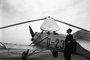
Cierva C.19
| C.19 | |
|---|---|
 |
|
| Cierva C.19 Mk IV (Avro 620), D-2300 ex-G-ABUE | |
| Role | Utility autogyro |
| Manufacturer | Cierva |
| Designer | Juan de la Cierva |
| First flight | 1929 |
| Number built | >30 |
The Cierva C.19 was a 1930s British two-seat autogyro, designed by Spanish engineer Juan de la Cierva. It was built by Avro as the Avro Type 620. It proved to be the most successful and widely produced of the early de la Cierva designs.
De la Cierva's first successful autogyro, the Cierva C.6, used an Avro 504 fuselage, and this led to a long and close collaboration between de la Cierva and Avro from 1926 onwards, with de la Cierva providing the rotor design, and Avro the airframe from designs that often appeared as both fixed-wing and rotary aircraft. There was a long series of such autogyros, developing the rotary wing concept. However the 1929 C.19, was a de la Cierva design, owing nothing to existing Avro aircraft, though it was built by Avro at Hamble.
Like the earlier aircraft, the C.19 had a conventional airframe, a two-seat fuselage carrying a small span wing with ailerons (to relieve rotor loads in level forward flight), and a single radial engine in the nose. The unpowered, free-spinning rotor had four wire-braced blades, or three cantilever blades in the Mk IV, and was mounted on four struts over the forward cockpit which met together to form a pyramid. The C.19 Mk I - IV did not have the tilting rotor head and associated hanging control column of later autogyros like the Cierva C.30. Instead, control was by the ailerons, elevators and rudder via a conventional column, a system that only worked effectively when the airspeed was high enough.
A major engineering refinement in the C.19 was the means to mechanically start the main rotor spinning; in earlier de la Cierva designs, the rotor had to be turned by hand or by pulling a rope, unless there was space for a take-off run. In the C.19 Mk I, this was done aerodynamically. The tail unit of this mark was a biplane structure with end-plate fins and rudders. To start the rotor, elevators and tailplanes were fixed in a near vertical position and the engine started. The wash from the propeller was deflected upwards by the tail unit through the rotor, rotating it. For the first time, this made the autogyro independent of ground crew at start, and private ownership was a practical proposition.
The 80 hp (60 kW) Armstrong Siddeley Genet II made the Mk I machine underpowered, and it was replaced in the C.19 Mk II by a 105 hp (78 kW) Genet Major I. The C.19 Mk IIA, introduced in 1930, had a longer travel undercarriage and improved rotor head. Often landings were made at high angles of attack, so the rudders of the C.19 Mk III were reshaped to slope sharply upwards to avoid damage; this variant also had a 5 ft (1.52 m) increase in rotor diameter.
...
Wikipedia
